Property Editor: Design Sheet
When you create a new Graphic Report, a default design sheet is added. If the report will need different page layouts, you can add multiple design sheets and set the properties of those sheets in the Design Sheet Property Editor.
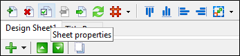
To open the Property Editor, click the Sheet Properties button (or right-click on the sheet and select Properties from the right-click menu).
Identity
Enter a Name for the Design Sheet and a short Description that identifies its purpose. The name of the sheet may identify the content of the report. If you have multiple design sheets, each name will identify a section of the report.
The name you enter is displayed as a tabbed page in the Designer List window.
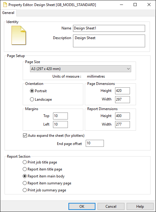
Page Setup
Set the page size and orientation and the width and height of the design sheet. You may require a different page orientation, margins, or sheet dimensions, for each section of the report (see below). For output to a plotter, you can also vary the page length.
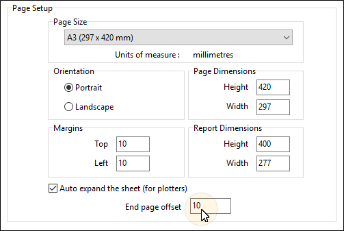
Auto expand the sheet (for plotters)
Select this option to auto-expand the height of the page based on the drillhole depth.
Although you may have defined a report with a vertical scale (depth of hole) which fits most pages, since the depth will vary from hole to hole, you can select this option to change the properties of the page to ensure the hole will always fit onto one page when printing to a plotter.
To create a footer between the end of the hole data and the end of the page, you can set an End page offset (in the units of measure defined for the selected page size).
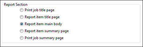
Report Section
Select the Report Section that the design sheet applies to. You can add a new design sheet for each section of a report. Margins may differ, for instance, between the Title page of a report and the report's main body.