Calculated Fields
Applying a default compositing method to all numeric fields will be satisfactory in most cases. If not, you can use the Calculated Fields tab to apply other methods to individual fields. It is important to remember the two cases where none of the compositing methods will return the correct result. These are:
- The coordinate fields—the East, North and Z or each sample interval mid-point.
- The thickness field—the length of each interval (TO—FROM).
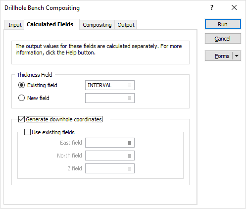
If your Interval file contains coordinate or thickness fields you can control how they are processed. On the Calculated Fields tab. You can:
- Determine if the differences between the From and To values for each interval in the output file will be written to a Thickness field, and if so, the name of the field where they will be written.
- Define the name of a Drillhole Database. The compositing function will use the database to generate the coordinates at the centre of each interval and then write them to the output file.
- Alternatively, use existing coordinate fields in the Input file.
Existing Thickness field
By default, the compositing functions will process the values of the thickness field in the input file, apply the default compositing method, and write composited values to an identical field in the output file.
Double-click to display a list of the fields in the input file and select the field where the thickness values will be written.
If you enter the name of the Thickness field in the input file (Source file A in the case of Interval Compositing) the function will use the name and parameters of that field when it creates the new field in the output file. If you specify a new name, the function will use the parameters of the To field when it creates the field in the output file.
New Thickness field
When you select this option, the thickness field in the input file is still written to the output file. If you enter the name of a new field, this field will be added as an additional thickness field to the output file.
Generate downhole coordinates
Select this option to define trace coordinates as part of a Drillhole Database, and optionally write those coordinates to the Input file.
3D coordinates are needed whenever an Interval file is used in a process where the locations of the intervals must be known. Some examples are resource estimation assignments using outlines. 3D coordinates are also required in various Compositing functions.
Use existing fields
New coordinate fields will be created unless you choose to use existing fields. The name, width and precision of the new fields will be the same as those used to define the location of the collars.
To use existing fields in the Input file, select the Use Existing Fields check box.
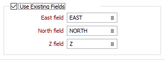
East and North and Z fields
If you have chosen to use existing fields in the Input file, specify the names of the fields in which the Easting, Northing, and Z coordinates will be stored.