Use the File | Export | DXF (AutoCAD Ver.12) function to export point and line data to a DXF file (DXF is an acronym for Drawing Exchange File).
Data type
In the Export DXF Files form, select a (2D POINTS, 3D POINTS, 2D STRINGS, 3D STRINGS) data type option from the drop-down list provided.
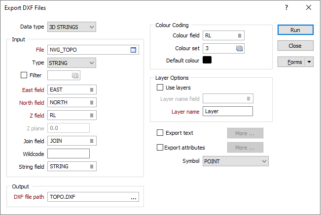
Input file
Select a (DATA, SURVEY, STRING, PIT DESIGN, ODBC LINK or MDB LINK) file type and then double-click (or click on the Select icon) to select the name of the File to be exported. If required, define a filter to selectively control which records will be included in the export process.
East, North and Z fields
If you have chosen to export 3D POINTS or 3D STRINGS, enter (or double-click to select) the names of the fields that contain the Northing, Easting and Z values.
Z plane
If you have chosen to export 2D POINTS or 2D STRINGS, the Z field is not required. Instead you must enter a constant Z value. The default value is 0.0.
Join field
In forms that require polylines as an input, the values in this field define whether the data points in the input file should be joined by a line. If successive records have the same value in this field, a line will join the points. If two-factor topology is required, the values in a String field may also be used to segment the lines.
Wildcode
Enter the value (usually characters) in the String field that will force a line to be drawn to both the previous and next point. The line type will be that of the previous or next point. A wildcode used to join CREST and Toe strings, for example, might be CT.
String field
In most forms, the String field is an optional generic attribute used to store a secondary input such as a code. Traditionally, this field has also been used with the Join field to define whether data points should be joined by a line, or strung, hence the name.
Symbol
From the Symbol list select a symbol that is to be displayed at each point.
Colour field
Double-click (or click on the Select icon) to select the field in the input file that contains values which will determine the colour of the lines. The colour set, that is associated with this field, maps colours to text strings or numeric ranges. For each record in the file, the display colour is determined by the value in this field.
Colour set
Double click (F3) to select the set that will be used to control the display colour. The colour set maps colours to text strings or numeric ranges. This determines the colour for each value in the colour field. Right click (F4) to create or edit a colour set.
Default colour
Double click (F3) to select the colour which will be used when a colour set is not defined, or when the value in the colour field is not mapped in the colour set.
Use layers
Select this option to define LAYERS in the DXF file based upon the unique values of a field in the file. Double-click (or click on the Select icon) to select the name of a Layer field in the file.
If you want to export data to a single layer, leave the Use layers check box blank and just enter a Layer name.
Export text
To export text, select this check box and click the More button. See: Exporting text to a DXF file
Export Attributes
To export attributes, select this check box and click the More button. Double-click (or click on the Select icon) to select the fields in the input file that will be written as attributes to the output DXF file.
Output file
Enter (or double-click to navigate to) the path and filename of the output DXF file.