3D Seismic (SEG-Y)
Seismic surveying is an essential tool for stratified deposits such as coal. Seismic data is easily combined with drillholes in Micromine, providing another layer of information and improving the quality of the resulting models.
Vizex supports the 2D and 3D SEG-Y formats used by geophysicists.
-
The 2D Seismic (SEG-Y) layer supports common processing options like manual adjustments, automatic gain control and vertical depth/time adjustments. Display options such as trace thickness, colour and fill make it easy to produce a visually informative display.
-
The 3D Seismic (SEG-Y) layer supports processing options for in-line and cross-line sampling. Colour, 3D Shaded and 2D Slice draw styles, and layer transparency, can all be applied to the model. An option to generate isosurfaces around discontinuities detected during seismic interpretation, is also provided.
Select File | Import | 3D Seismic (SEG-Y) to import a 3D Seismic (SEG-Y) file and generate an output Volume file that can be displayed in Vizex. The 3D SEG-Y-file format is one of several standards developed by the Society of Exploration Geophysicists for storing geophysical and Seismic Data.
Input Data
SEG-Y File
Double-click (or click on the Select icon) in the File box to select an Input (*.sgy, *.segy) file. You can right-click in the File box to display basic information about the file (the revision of SEG-Y, the sample count, the sample interval from the Binary Header, and the text in the basic Text Header).
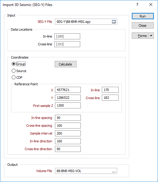
Data locations
Specify the location of the In-line and Cross-line headers that define the extents of the volumes you want to import. By default, in-line and cross-line headers are placed at bytes 189 and 193 respectively in a Revision 1 SEG-Y standard file.
If the file you are importing does not conform to this standard, you may need to view the EBCDIC Header in the file and modify these default values
Coordinates
Select an option that will be used to obtain the X/Y coordinates of each trace and click the Calculate button to calculate the tie-points. There are three options:
- Group: (bytes x=81-84, y=85-88)
- Source: (bytes x=73-76, y=77-80)
- CDP: (bytes x=181-184, y=185-188) Revision 1.0 only
The values from these bytes will be modified by the coordinate scalar at bytes 71-72.
Reference point
Enter X, Y and first Z coordinate values (tie points) that define the relationship between the In-line and Cross-line spacing values in the file, and real-world coordinates.
You can find these coordinate values in the EBCDIC Header of the file (press F4 in the Input file box to view a summary of the file).
If they are available, surveyed coordinates will be more accurate than the tie points automatically calculated by clicking on the Calculate button, and which relies upon the correct mapping of the X/Y trace headers in the file.
In-line and Cross-line spacings and intervals
Enter spacing and interval values to determine the coarseness of the sampling. Each interval should be a multiple of the corresponding spacing.
To load a coarser sampling of the data, increase the interval size.
Sample Interval
This value comes from the binary header.
In-line and Cross-line directions
Enter direction (bearing) values to determine the direction of sampling. The angle between the In-line direction and the Cross-line direction must be perpendicular.
Output
Volume file
Enter the name of the Volume (*.mmvol) file that will be created as a result of the import process. To overwrite an existing file, double-click (F3) to navigate to the location of the file.
You can view the output from this function by selecting Display | 3D Volume.
For more information, see: Display SEG-Y