CAD Cursor

|
Click the CAD Cursor button on the String Editor toolbar to toggle the CAD Cursor display on or off. Note that the CAD cursor is only visible when an appropriate (Select Tool, Measure Tool, etc.) mouse mode is being used. |
| To change the display settings of the cursor, use the drop-down tool menu: | |
|
Display CAD Cursor
Select the check box to enable the CAD Cursor display:
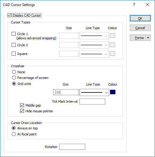
Cursor Types
To customise the cursor, select a combination of circle and square shapes, including the option to snap lines to the edge of Circle 1 (advanced snapping). This only works when you are creating new points or lines in Snap to Line mode, or dragging points with the default selection tool in Snap to Line mode.
Set the line type the size , and the line colour of the circles and square shapes you have selected.
The size of the circles and the square are defined by radius.
Crosshair
Choose whether or not to display a crosshair. The crosshair can be measured as a percentage of the screen, or as a specified length (the default is 10) measured in grid units.
If you have chosen the latter, you can specify an interval to display tick marks along each axis.
Set the line type the size , and the colour of the crosshair lines.
Use the Middle gap check box to enable or disable the gap in the middle of the crosshair
Select the hide mouse pointer option to disable the default windows cursor when using the default selection tool.
Cursor Draw Location
Choose whether the cursor will be drawn always on top of display objects or be drawn at the focal point, cutting through objects depending on their relative depth.
When vertical exaggeration or perspective mode are turned on, cursor shapes are not visible. A crosshair will only be visible when the crosshair mode is Percentage of screen.