Orthogonal
Use the Orthogonal tab of the Display Limits form to define an orthogonal view of your data.
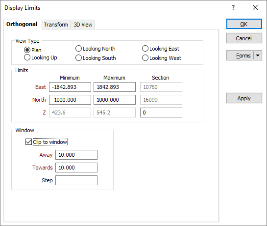
Traditionally, the term orthogonal means pertaining to or composed of right angles, and is used here to describe the orientation of a view which is either Plan, Looking Up, Looking North, Looking South, Looking East, or Looking West.
View Type
You can view your data in plan and section using one or more windows. Select an option, for example, Looking North or Looking East, to determine the section line. The View Type you select will be applied to the current (active) window.
Most drillhole sections are viewed from the south (a North section, i.e. Looking North) or the East (a West section, i.e. Looking West). Both of these views will have the X axis coordinates of the display increasing from left to right across the screen and any plotted (scaled) output will reflect this.
In some locations, sections are viewed from the North or the West. In these cases the maximum X coordinate is on the left of the screen or plotted output. When generating sections looking South or East, the plot will have a -ve X scale. This forces the plotted output to have the maximum X coordinates on the left hand side of the plot. Do not delete the -ve sign. If you do, the plot will be rotated laterally (mirror imaged).
You can also switch View Type using the display orientation buttons on the View toolbar.
Limits
You can view your data using different extents of display limits. The Limits you define will be applied to the current (active) window.
- When you choose LOOKING EAST or WEST, the North min/max and the East section prompts are enabled. When you choose LOOKING NORTH or SOUTH, the East min/max prompts and the North section prompts are enabled. In both cases the RL min/max will be enabled.
- When you choose PLAN or LOOKING UP, the North min/max, East min/max and Starting RL prompts are enabled.
Clip to Window
Select the Clip to window option to restrict the display to a window which is defined using measurements towards and away from the current RL value.
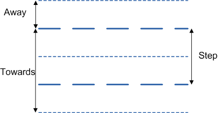
Window Towards and Window Away
The values you enter in Window towards and Window away define the width and position of the data corridor (the “thickness” of the slice).
- In Plan view, Window towards is a measurement taken from the nominated level towards the viewer. Window away is a measurement taken from the nominated level away from the viewer.
- In Section view, Window towards is a measurement taken from the section line towards the viewer. Window away is a measurement taken from the section line away from the viewer. See Window Towards/Window Away
If you have not previously set default Away and Towards values, the default values specified in the Clipping tab of the Tools | Vizex | Options form will be shown.
A preview of the section line is displayed in the preview pane, based on the parameters you have entered.
Step
In the Step input box, set the distance to be moved from the Next Section/Previous Section.
If Step = Away + Towards
This is the default step value, which is shown on the Vizex Sections toolbar in square brackets. Whenever you change the Away or Towards values, the Step value is automatically updated.
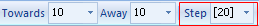
As long as Step = Away + Towards, the Step value on the Display Limits form is left blank until the user specifically enters a value.
But what if you want to increase the Window Towards value and keep the Step value unchanged so that you can, ![]() for example, step to the next section but still see the previous section?
for example, step to the next section but still see the previous section?
If Step <> Away + Towards
This is a non-default step value, which is shown on the Vizex Sections toolbar without square brackets. If you change the Away or Towards values, the Step value is not updated.

When Step <> Away + Towards, the Step value is shown on the Display Limits form.