Polyline Section Tool
 Select View | Sections | Define Polyline Section (or click the Polyline Section tool on the Vizex Sections Toolbar) to define a polyline section (fence) view comprising multiple segments.
Note: If a valid string is selected when the tool is invoked, the string is used to define the section.
Polyline Sections may be drawn in any position and may include any supported Vizex data. Normal towards/away distances apply and a very limited number of editing tools are also available.
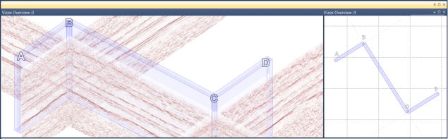
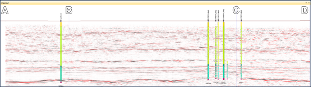
If only two points are specified, a regular section view is created. If three or more points are specified, a Polyline Section view is created. Limited string editing is enabled, as well as panning/zooming using the middle mouse button. A scale bar and orientation axis can be added to the view, and a plot or screenshot of the sections may be generated.
To create a polyline section from a string:
- Load the relevant data into Vizex (any Vizex type) and ensure the view orientation is set to Plan.
- Load and select the string you want to use to create the section.
- Select View | Sections | Define Polyline Section (or click the Polyline Section tool on the Vizex Sections Toolbar).
Vizex will display a new window containing the section.
To digitise a new polyline section:
- Load the relevant data into Vizex (any Vizex type) and ensure the view orientation is set to Plan.
- Select View | Sections | Define Polyline Section (or click the Polyline Section tool on the Vizex Sections Toolbar).
- You will be prompted to digitise a point at each bend in the section, optionally snapping to other data.
- Right-click or double-click to finish the section. Vizex will display the section in a new window.

To edit a polyline section:
- Select View | Sections | Define Polyline Section | Polyline Section to open the Polyline Section form:
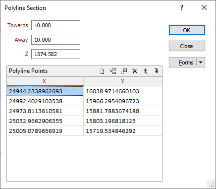
A section you have created interactively, or created from a string, can be edited here.
Towards and Away
The values you enter in Towards and Away define the width and position of the data corridor (the “thickness” of the section).
In Plan view, Window towards is a measurement taken from the nominated level towards the viewer. Window away is a measurement taken from the nominated level away from the viewer.
Forms
Click the Forms button to select and open a saved form set, or if a form set has been loaded, save the current form set.
By design the Forms button is not available for loaded Vizex layers (i.e. when opening the form set properties of a layer in the Display Pane). In Vizex, the Forms button is only available for new forms opened via the Display | Vizex menu (or by double-clicking on a form type node in the Vizex Forms Pane).
Save and Save As
Click the Save button to save the changes you have made to the form set. Click Save As to save your changes as a new form set. Save As will default to the first available form set number.
Reset
Click Clear to clear the form of all values and reset the form to its default state. In the case of tabbed forms, set the first tab as the active tab.
Undo and Redo
Click Undo (CTRL + Z) to undo recent changes in the form. After an Undo, click Redo (CTRL + Y) to restore the last change that was undone.
Collapse
Collapse (roll-up) the form to preview the results of an operation in Vizex, or obtain input values from Vizex, the Property Window, the File Editor, or the Plot Editor.