On the Block Model tab of the DTM Assign | Block Model form, you can choose to:
- assign attributes to blocks that are completely or partially above or below a DTM;
- assign a code to blocks considered to be outside of the DTM, based on an outside cut-off value;
- delete data outside of the chosen assign region
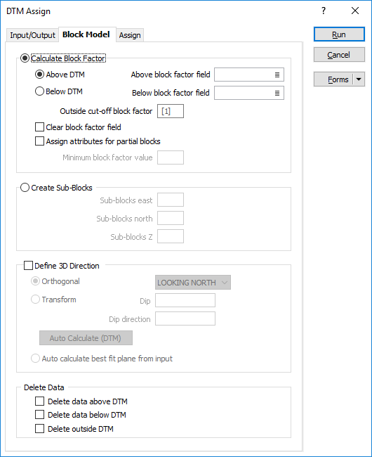
Calculate Block factor
If you select the Calculate Block Factor option, a Block Factor is used to define the portion of each block that falls within the assign region you have defined.
Choose whether the assign region is Above or Below the DTM.
Above and Below block factor fields
Double-click (or click on the List icon) to select Above and Below block factor fields. The portion of each block that falls above and below the assign region are written to this field.
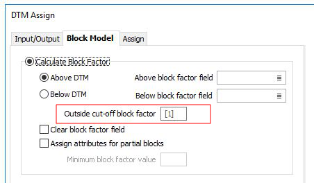
Outside cut-off block factor
If blocks that are partially outside the assign region are to be coded as outside, specify an outside cut-off value less than 1. The default is 1. In other words, a block must be fully outside of the assign region before it is classified as outside.
Clear block factor field
The Block factor field can be cleared of all values before the function makes any assignments.
Assign attributes for partial blocks
Select this option when you are working with a block model and want to assign attributes to blocks that are only partially above or below the DTM.
Minimum block factor value
Optionally enter a minimum value for the block factor. For example, you may only want to assign values when at least 20% of the block is above or below the DTM.
If no minimum block factor value is specified, the attributes are assigned whenever the factor value is greater than zero. Otherwise, the attributes are assigned if the factor value is greater than or equal to the specified minimum value.
Create sub-blocks
Sub-blocks East, North, Z
If you select Create Sub-blocks as the sub-blocking method, enter the number of sub-blocks, into which the block will be subdivided in each direction. The number of sub-blocks must not exceed 25 in each direction.
The more sub-blocks there are, the more accurate the assignment will be - at the expense of processing speed.
Block Size fields will typically be of type DOUBLE and have enough precision to accurately store the sub-block data. In the case of Numeric fields, numerical rounding may cause block overlaps and other inconsistencies in the data.
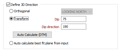
Define 3D Direction
The Define 3D Direction option allow you to choose a non-plan reference plane which will provide better results when assigning
Specify an Orthogonal (LOOKING
WEST, LOOKING NORTH, PLAN) or Transform
reference plane that will determine the direction in which the
Orthogonal
In Orthogonal mode, the Code value prompts on the Assign tab will change to reflect which
For non-orthogonal mode, "above" means above the plane, unless the plane is vertical, in which case "above" is to the north. However, if the plane is a vertical north-south plane, "above" is to the east.
Transform
In Transform mode, Dip and Dip Direction transform parameters are taken from the screen plane orientation (on the 3D View tab of the Display Limits form). Auto Calculate (DTM) will set these parameters to match the mean normal of the surface.
Auto calculate best fit plane from input
Select this option to calculate the best plane of fit from the input data.
For more information, see: Defining the 3D direction
Delete Data
Optionally, choose to delete data which is above, below, or outside the DTM.