Import Points and Lines
The Points and Lines tab of the Import CAD form is enabled if the input file contains point and line features. Select the Import Points and Lines check box to enable the import.
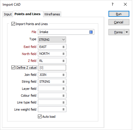
File
Enter (or double-click (F3) to select) the name of the target file to which the point and line data will be written.
Easting, Northing, Z fields
Specify the names of the fields to which X, Y and Z coordinates will be written.
Define Z value
Select this option to define a Z value for the imported points and lines.
Join field
(Optional) Specify the name of the field containing values which define whether data points will be joined by a line i.e. strung. If successive records have the same value in this field and no String field is defined, a line will join the points. If a String field is defined, then values in each field in successive records must be the same before the points will be strung.
String field
(Optional) Specify the name of the field containing values which define whether data points will be joined by a line. The values of this field in successive records must be the same before the points will be strung.
Layer field
Specify the name of the field that will contain values which can be used in subsequent file operations to filter the data based upon a particular feature type (layer).
During import, the AutoCAD layer name is written to this field. The import process will enumerate through the layer names to obtain a maximum width for the field.
Colour field
(Optional) Specify the name of the field to which the imported point and line colours will be written. These values will be used to colour-code the display when the Auto load check box option is selected.
The selected field must be a formatted Colour field.
Auto load
To display the data in Vizex once the file has been imported, select the Auto load option.