Floor Wireframe
Use the Mining | Underground Design | Floor Wireframe function to generate a declined or multi-level surface wireframe from the strings or points in a file.
Input
File
Select a file type and then double-click, or click on the Select icon, to select a file that contains the strings or points you want to create a surface from. If required, define a filter to selectively control the records to be processed.
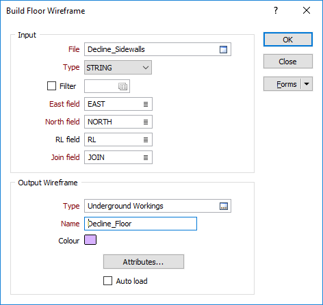
East and North and RL fields
Specify the names of the fields in which Easting, Northing, and RL coordinates are stored in the string file.
String field
Specify the name of the field that contains values that define whether data points should be joined by a line. The values of this field in successive records must be the same before the points will be strung.
Join field
Specify the name of the field that contains values that define whether data points should be joined by a line i.e. strung. If successive records have the same value in this field and no String field is defined (see above) a line will join the points. If a String field is defined, then values in each field in successive records must be the same before the points will be strung.
Output Wireframe
Type and Name
Specify the type and name of the generated wireframe.
Colour
Specify a default display colour for the generated wireframe.
Attributes
Click the Attributes button to set standard and user-defined attributes for the wireframe. When you save a wireframe, you should set standard attributes (colour and title settings etc.).
Auto load
Select this option to load the generated output in Vizex. The default draw style for an auto-loaded wireframe is 3D Shaded.
Forms
Click the Forms button to select and open a saved form set, or if a form set has been loaded, save the current form set.
Run
Finally, click Run to run the process.