Working with tie lines
Tie lines are used to define the control points for the depth adjustment function. A tie line links a current depth (in an adjustable source panel) to a target depth (in a reference panel). The current depth will be equal to the target depth after the depth adjustment has been performed.
Create a tie line
Click the Add normal tie line button on the toolbar, then click on the appropriate depth in any adjustable panel.

Keep the mouse button down and drag the line indicator to the corresponding target depth in any of the reference panels (or vice versa). Once the mouse button is released, the new tie line will be displayed at the appropriate position in the tie line column. To cancel the process, release the button while the mouse cursor is over an invalid destination panel.
Select a tie line
To select a tie line, click on the small square at the centre of the tie line. Alternatively, click on the tie line entry in the list view at the bottom of the window. Once a tie line has been selected you can use the right-click menu, or toolbar to interact with the tie line.
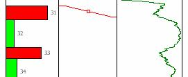
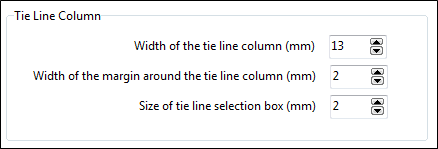
The width of the tie line selection box is set when the depth adjustment process is configured.
Snap to depth boundaries
By default, the start and end points of a tie line will "snap" to the nearest depth boundaries in the source panel when the tie line is created; however, if you drag the line indicator to the corresponding target depth in a reference panel of type Column, they will snap to the nearest depth boundaries in that reference panel.
You cannot snap to a reference panel of type Graph.
In some cases, snapping to the nearest depth boundary may not be the desired behaviour. You can toggle the snap tool on and off by clicking the Snap button on the toolbar.

Alternatively, you can temporarily disable the snap tool by holding down the CTRL key before clicking the mouse button to define the tie line.
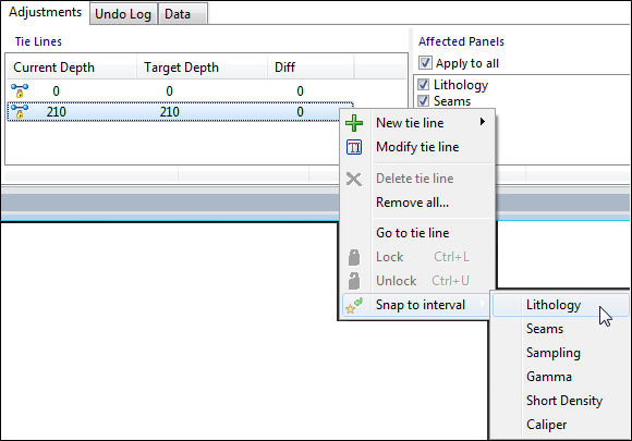
The currently selected tie line can also be snapped manually by using the Snap to interval options on the right-click menu. Choose the panel to snap to from the list provided in the sub-menu.
Delete a tie line
To delete a tie line, select it and click the Delete button on the menu, or select Delete Tie Line from the right-click menu.

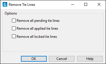
Alternatively, right-click and select Remove All to select which tie lines to delete:
 Use fixed tie lines to retain the interval
width
Use fixed tie lines to retain the interval
width
To prevent changes to the width of a selected interval, click on the appropriate depth interval (or gap), then click the Add fixed interval tie line button.
The system reacts by inserting a parallel tie line at the appropriate contact of the selected unit (or at both contacts, if necessary).
The system will automatically find the most suitable tie line to act as a reference (anchor) for the new tie line. If either of the contacts fall on a tie line, then this tie line will be used as the anchor. Otherwise, the closest tie line above or below the selected interval will be used.
Create “locked” intervals
Locked tie lines are used to limit or prevent changes to depths along certain sections of the drillhole. You can create a locked tieline by selecting the Add locked tie line button on the ribbon.

A lock point is defined by creating a tie line with identical current and target depths (i.e. a horizontal tie line). This point is effectively fixed and will not be moved as a result of the depth adjustment process.
To ensure that the current and target depths for a given tie line are exactly the same, select the tie line and click the Lock button on the ribbon.
You can also create a lock point by holding down the Shift key when using the mouse to define the tie line. (Combine Shift with Ctrl to override snap behaviour.)
Locked tie lines usually operate in pairs, effectively creating a locked section. Changes made to depths within this section will not affect intervals above or below the locked points.
Two locked tie lines are defined automatically when the datasets are opened: one at zero depth and the other at the end of hole (or the maximum depth returned by the queries, whichever is appropriate). Further lock points should be added manually before any depth adjustments are made. This will ensure that the effects of the adjustments are limited to appropriate sections of the drillhole.
Create "Split" Tie Lines
To create a split tie line, select the "first leg" of the tie line and then click the Add split tie line button.

A split tie line is a special type of tie line that is used to insert a gap at a depth boundary. A split tie line consists of two tie lines that have the same current depth but different target depths.
Once a gap has been created, this is usually followed by an insert.
The difference between this type of insert and the normal "Insert Interval" is that the split tie lines can be used in conjunction with other tie lines. In other words, the effect of the insert can be spread over several intervals, unlike a normal insert operation which affects only one or two intervals.
This method ensures that the current depths for both tie lines are identical, thereby identifying the two lines as a split pair. Once this relationship has been established, the common current depth will be maintained. The split tie line can be converted back to a normal tie line by deleting either of the paired lines.
A split tie line will only operate on depth boundaries that match the current depth of the tie line exactly. If there is no match, the tie line will be ignored.
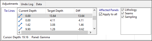
Limit the effect of tie lines to certain panels
The check list at the right of the Adjustments pane (next to the list of tie lines) is used to indicate which panels are affected by the selected tie line.
By default, a tie line applies to all adjustable panels in the panels list; however, the influence of any individual tie line can be changed by selecting or deselecting the check boxes for the appropriate panels. This determines whether the selected tie line will be included as a control point in the depth adjustment function for any given panel.
Options on the Panel Setup: Editing tab of the Panel Property Editor can be configured to limit the effect of new tie lines on any given panel.
Navigate to invisible tie lines
Some tie lines may fall outside the visible depth range. To navigate to one of these tie lines (without scrolling), select the corresponding row in the list view at the bottom of the window, then select Go To Tie Line from the right-click menu.
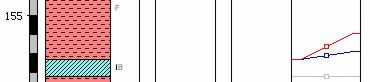
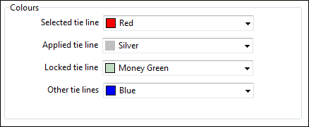
Display colours for tie lines
The display colours for tie lines are set when the depth adjustment process is configured. By default, the selected tie line is displayed in red, while other tie lines are displayed in blue or grey, depending on their state.
Adjust depth intervals using tie lines
Tie lines can be applied in one of two ways: individually, or as a group. These two methods are fundamentally different, therefore it is very important to understand the way in which each operates.
Apply a selected tie line
Click the Apply selected tie line button to make adjustments based on the selected tie line.

When a single tie line is applied, it will adjust only those depths (in the adjustable panels) that are exactly the same as the current depth setting for the tie line.
The fact that the tie line is used in isolation means that this operation has certain limitations, viz:
- A single tie line can only operate on an actual depth boundary, since the depth value in the adjustable dataset needs to match the current depth value exactly.
- The resulting depth adjustment is limited to a single depth boundary; i.e., the selected boundary can be moved up or down, but it cannot be moved beyond the next depth boundary above or below it. (When this happens, you need additional tie lines to control the expansion or contraction of intervals above and below the changed section.)
To adjust a depth boundary using a single tie line:
- Create the tie line by linking the adjustable depth boundary to a target depth in one of the reference panels.
- Click the Apply selected tie line button.
All depth boundaries that match the current depth value of the tie line will be changed to match the target depth. The display will change accordingly to indicate that the adjustments have been performed successfully across all affected panels. The colour of the tie line will change to grey, indicating that it has been applied.
This tie line is now horizontal and effectively becomes a locked point.
Apply all tie lines
Click the Apply All Tie Lines button to make adjustments based on all the available tie lines.

When tie lines are applied as a group, every tie line effectively becomes a control point on the depth adjustment graph. When the function is applied to the downhole data, depth readings that fall between the tie lines are interpolated from the graph (as explained in the depth adjustment overview).
It is important to NOTE that all the depth boundaries in the affected panels will be adjusted according to this function. This emphasises the need for proper control via "locked" points along the depth profile. You should ensure that all tie lines are in the correct positions before they are applied.
The display will change to reflect the changes caused by the adjustments. This indicates that the process has been executed successfully across all panels.
The colour of the applied tie lines will change to grey to indicate their new state. The tie lines are now horizontal and have effectively become locked points.
 Undo an Apply action
Select the Undo Log tab see a list of changes resulting from the adjustment. You can cancel the effects of the adjustment by clicking the Undo button on the toolbar.
Minimum Width
When the depth adjustment is applied, individual depth intervals may be contracted or expanded, depending on the relative positions of the tie lines. In order to prevent small intervals from being “lost” in the process, it is necessary to place a minimum limit on the width of an interval.
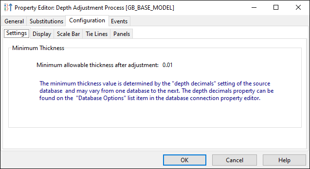
The minimum thickness value is determined by the "depth decimals" setting of the source database, and may vary from one database to the next. The depth decimals property can be found on the Advanced | Professional page of the Database Connection Property Editor.