Point Cloud Modelling
Select Modelling | Implicit Modelling | Point Cloud to create a surface using points resting exactly on an open or solid surface. The output is a wireframe of the surface.
The file specified on the Input tab of the Point Cloud Modelling form will be a data file which contains the control points that define the surface or the volume to be modelled.
Input
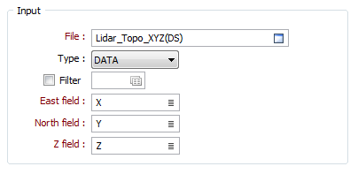
File
Double click (or click on the Select icon) to select an Input file. Typically, the Input file will be a String or a Data file that defines the surface to be modelled.
East, North and Z fields
Specify the names of the fields in which Easting, Northing, and Z coordinates are stored in the points file.
Implicit Model
Enter (or click on the ellipsis button to select) the name of an Output file.
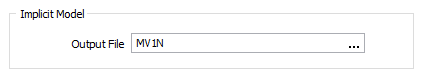
Tip: An Implicit Model (*.im) file can be used as an input to the Modelling | Implicit Modelling | Output Implicit Model function. This allows you to generate different output triangulations or points for the same model, without having to recompute the model each time.
Output Wireframe
In the Output group of the Point Cloud Modelling form, you can write the implicit model to an output file and generate wireframe output.
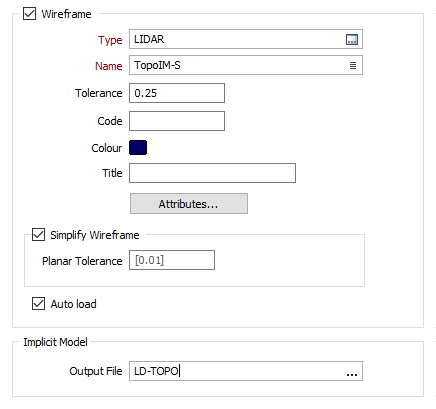
Type and Name
Double-click (F3) to select the Type and Name of the Output wireframe.
Tolerance
Specify a tolerance (in Grid units). The surface extracted from the implicit model is done to the accuracy defined by the tolerance, such that the difference between the wireframe surface and the theoretically perfect mathematical model falls within the measured tolerance distance.For example, if the wireframe is a plot of the zero-level contour of an implicit model and the tolerance is 0.1 then the true values of the implicit model at all points on the wireframe would be in the range [-0.1, +0.1].
Code
Enter a Code that can be used to differentiate between the wireframes generated as a result of this process. If no Code Field has been assigned (or Code values are missing) from the input file, the Code value you enter here will be assigned instead.
Colour
Double click (F3) to select the Colour that will be used to display the generated wireframe.
Title
Enter a meaningful Title for the wireframe you are creating.
Attributes
Click the Attributes button to set attributes for the wireframe output.
User-defined attributes may be mapped against the fields in the Input file. It is also possible to specify a default value for each attribute. Default values are used when a corresponding value in the Input file is either missing or is not mapped.
Auto load
Select this option to load the generated output in Vizex. The default draw style for an auto-loaded wireframe is 3D Shaded.
Simplify Wireframe
Select this option to reduce the number of vertices in the triangulation by eliminating those points that can be removed without causing the triangulation to move by more than the specified tolerance values:
- Planar Tolerance. This is the maximum amount that the triangulation is allowed to move in any direction after vertices are removed.
Note: If no planar tolerance is specified, a default value of 0.01 will be applied automatically. Specifying a large planar tolerance will significantly alter the nature of the triangulation.
Forms
Click the Forms button to select and open a saved form set, or if a form set has been loaded, save the current form set.
Run
Click Run to run the function.
Note: To better utilise processor resources across multiple applications and tasks, when running computer-intensive operations it may be necessary to use the Advanced tab of the Tools | Options | Vizex form to reduce the number of cores used by Micromine.