Hatching
Use the options provided on the Hatching tab to apply hatching to the drillhole intervals.
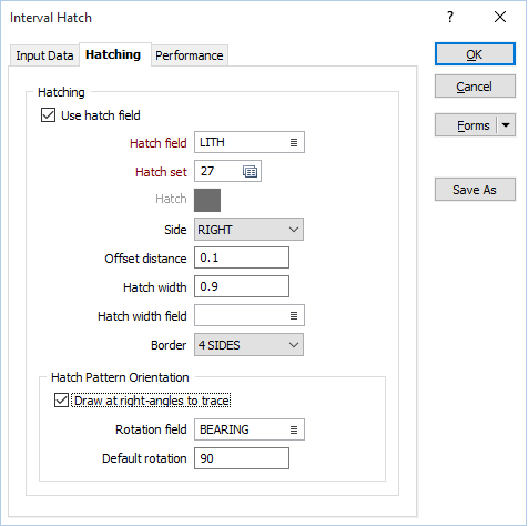
Use hatch field
Select this option if you want to apply a hatching to the polygons in the display.
Hatch field
Enter the name of the field (in the file) containing the data that will control the hatching. The hatch set associated with this field maps hatch patterns to text strings or numeric ranges. For each record in the file, the hatch pattern that will be used is determined by the value in this field.
Hatch set
Double click (F3) to select the set that will be used to control the hatch pattern. The hatch set maps hatch patterns to text strings or numeric ranges. This determines the hatch pattern for each value in the hatch field. Right click (F4) to create or edit a hatch set.
Hatch
Double click (F3) to select the hatch which will be used when a hatch set is not defined, or when the value in the hatch field is not mapped in the hatch set.
Side
The hatch can be displayed on the LEFT or RIGHT of the drillhole trace. Use Side to determine its location.
Offset distance
Define the distance, in grid units, that the hatch will be offset from the trace. The default is 1. Both positive and negative values are acceptable.
Hatch width
Enter the width of the hatched area. The width is defined in grid units. If grid units are metres, a hatch width of 1 (the default) will result in a hatch pattern one cm wide on a plot at a scale of 1:1000. A value of 2 will double the width of the hatched area; a value less than 1 will decrease the width of the hatched area.
The hatch width will be used when no hatch width field has been specified, or when values in the specified hatch width field are missing.
Hatch width field
Rather than define a constant value, you can use the values in a field to control the width of the hatched area.
The specification of a variable hatch width, for example, can be used to highlight different grain sizes (coarse, medium, fine) for coal.
For metals, a variable hatch width can be used to display assays down the hole without adding labels.
Double-click to select the name of the field containing the values that will be used to control the width of the hatched area. If no hatch width field is specified, or values are missing in the specified field, the specified hatch width value (or a default hatch width of 1) will be applied.
Border
You can setup borders around the hatching. If the hatching is butted up against the drillhole trace, choose 3 SIDES. This will ensure that the drillhole trace is not overwritten. If the hatching is entirely separate from the drillhole trace, choose 4 SIDES to enclose it completely.
Hatch Pattern Orientation
Draw hatch patterns at right-angles to trace
Select the Draw hatch patterns at right-angles to trace check box option to make the hatch pattern perpendicular to the trace rather than horizontal. You can apply this setting in addition to the Rotation field and Default rotation settings described below.
Rotation field
If a Rotation field is defined and the value in that field for a given record is valid and is not empty, the rotation of the hatch is set to the rotation value in the field for that record.
Double-click (or click on the Select icon) to select a field containing the values you will use to rotate the hatch pattern for each interval.
If the Draw hatch patterns at right-angles to trace check box is selected, this defines a starting orientation. In this case, the rotation defined in the Rotation field is applied as an extra rotation from the starting orientation.
Default rotation
If a Rotation field is defined and the value in that field for a given record is empty or is invalid, the rotation of the hatch is set to the Default rotation value you specify here.
If the Draw hatch patterns at right-angles to trace check box is selected, this defines a starting orientation. In this case, the Default rotation is applied as an extra rotation from the starting orientation.