Block Model
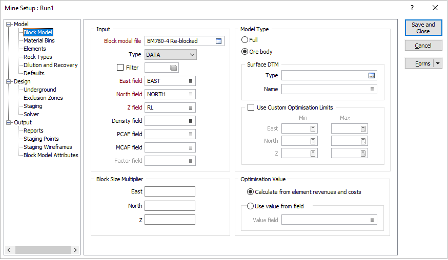
Use the Optimisation | Stope Optimiser | Mine > Definition | Model | Block Model page of the Mine Setup form to specify:
- Name of the file containing the block model for which the optimum stope layout is to be determined.
- Fields from which coordinates, densities, cost adjustment factors and block factors should be obtained.
- Whether the block model is a Full model, which includes all waste and ore for the region of interest, or an Ore body model, which typically contains only the ore component.
- Optional digital terrain model and custom optimisation limits for ore body model.
- Optional factors to be applied to block sizes in each direction.
- How the optimisation values for the blocks should be derived.
When deciding whether to use a Full model or an Ore body model within the Stope Optimiser, the following factors should be considered:
|
Consideration |
Full model |
Ore body model |
|---|---|---|
|
Missing blocks |
Treated as air. |
Filled automatically as required with waste blocks assigned properties in accordance with the Mine | Model | Defaults option. |
|
Surface DTM |
Not supported. Must already be restricted by air. |
Supported. Blocks above treated as air. |
|
Custom optimisation limits |
Not supported - optimisation region defined by extents of block model. Use exclusion zones. |
Can be defined by ranges of coordinates. |
|
Exclusion zones |
Sequenced inclusions/exclusions of wireframes or polygons define optimisation region. |
|
|
Factor fields |
Supported. |
Factored ore body models are NOT supported and should not be used. |
|
Block model rotations |
Azimuth rotations supported. |
Azimuth, Dip and Plunge rotations supported. |
|
Waste block properties |
Can be specified for each block. |
Values for all blocks specified by Mine | Model | Defaults option |
|
Availability of variable values in expressions |
COORD_X, COORD_Y, COORD_Z and <FIELD NAME> available only for blocks that exist in block model. See: Functions as Parameters |
|
|
Analysis |
Fully supported. |
Not supported directly – however, Optimisation Database supported. |
Tip: To minimise the potential for arithmetic anomalies caused by material classifications changing between nested stope layouts, it is recommended that Full models with Density field (or Tonnage factor field) specified be used wherever possible. If Density field (or Tonnage factor field) is not specified, or modelled values are not available (as may be the case for Ore body models), the default values for Ore Density and Waste Density specified on the Mine | Model | Defaults tab apply. If these values are significantly different, the change in classification of a block from waste in one nested stope layout to ore in the next nested stope layout may produce a significant change in the masses and element grades reported for that block.
Input
Block model file
Select the file containing the block model for which the optimum design is to be produced.
Sub-blocked models are supported. For the purposes of the optimisation, they will be regularised automatically as required. Results can be reported for either the regularised blocks or the supplied sub-blocks.
Type
Select the format (DATA / SURVEY / STRING / ODBC LINK / MDB LINK) in which the data for the block model is presented.
Filter
(Optional.) Specify the filter to be applied to the data in the block model.
Cut-Off Grades: Generally speaking, this setting should not be used to apply cut-off grades (because it removes the affected blocks from the block model completely). Cut-off grades should be applied by specifying an appropriate expression based on the source of the optimisation value as follows:
|
Optimisation Value |
Specify expression for Optimisation | Stope Optimiser | Mine > Definition | Model ... |
|
Calculate from revenues and costs |
Elements | Block Model field |
|
Use value from field |
Block Model | Optimisation Value | Value field |
East field
Select the field in the block model file from which the easting coordinate for each block should be sourced.
Expressions are not supported for this setting.
North field
Select the field in the block model file from which the northing coordinate for each block should be sourced.
Expressions are not supported for this setting.
Z field
Select the field in the block model file from which the Z (elevation) coordinate for each block should be sourced.
Expressions are not supported for this setting.
Density field
(METRIC projects, optional, recommended.) Select the field in the block model file from which the density for each block should be sourced.
For block dimensions specified in metres (m), densities must be expressed in tonnes per cubic metre (t/m3). Specific gravity values are suitable for this purpose.
If the block dimensions are specified in units other than metres (m), an appropriate conversion factor must be applied to the density values to ensure that the tonnages are calculated correctly. Since the Stope Optimiser does not know the units in which the block dimensions are specified, it cannot apply this conversion factor automatically.
Tonnage factor field
(IMPERIAL projects, optional, recommended.) Select the field in the block model file from which the tonnage factor for each block should be sourced.
Tonnage Factors must be specified in units consistent with those used for specifying the dimensions of the blocks in the model. No additional unit conversions are performed by the Stope Optimiser.
Using 1 foot = 0.3048 metres, 1 pound = 0.45359237 kilograms, and 1 short ton = 2000 pounds, Tonnage Factors expressed in cubic feet per short ton (ft3/sh tn) can be converted to cubic metres per tonne (m3/t) by multiplying by 0.03121398, or to cubic feet per tonne (ft3/t) by multiplying by 1.10231131.
PCAF field
(Optional.) Select the field in the block model file from which the Processing Cost Adjustment Factor (PCAF) for each block should be sourced.
The Processing Cost Adjustment Factor (PCAF) applies to costs that are incurred only if the ore is processed. The factor must be specified relative to the “standard block”, for which it is assumed that PCAF = 1.
If this field is left blank, or values are missing from the specified field, then the Default PCAF value defined in the Model | Defaults tab will be used.
MCAF field
(Optional.) Select the field in the block model file from which the Mining Cost Adjustment Factor (MCAF) for each block should be sourced.
The Mining Cost Adjustment Factor (MCAF) applies to costs that are incurred only if the block is mined – costs that stop when mining stops are not affected. The factor must be specified relative to the “standard block”, for which it is assumed that MCAF = 1.
If this field is left blank, or values are missing from the specified field, then the Default MCAF value defined in the Model | Defaults tab will be used.
The MCAF appropriate to the block’s classification as ore or waste will be applied to each block as required.
Factor field
(Optional.) Select the field in the block model file from which the block factor for each block should be sourced.
This field is disabled when Model Type | Ore body is selected. Ore body models with block factors are not supported and should not be used.
Tip: Block factors can be removed from block models by using Modelling | Block Model Tools | Regularise.
Model Type
Select the type (Full / Ore body) of block model supplied.
Full
Select if Full block model, which includes all waste and ore for the region of interest, is supplied.
Ore body
Select if an Ore body block model, which typically contains only the ore component for the region of interest, is supplied.
| Surface DTM | (Ore body model only.) Specify the digital terrain model (DTM) to be used to model the surface of the region of interest. This can be used to represent the topography or the extent of existing mining. |
| Type | Select the type of digital terrain model to be used to model the surface. |
| Name | Select the name of the digital terrain model of the specified type to be used to model the surface. |
| Use Custom Optimisation Limits | (Ore body only, optional.) Select to define the optimisation region by ranges of coordinates. |
| Min East, Min North, Min Z | Specify the easting, northing and Z coordinates for the lower extremity of the optimisation region. |
| Max East, Max North, Max Z | Specify the easting, northing and Z coordinates for the upper extremity of the optimisation region. |
Block Size Multiplier
When deriving optimum stope layouts for large models, particularly in preliminary testing of parameter configurations, it can be beneficial to combine full-size (i.e. not sub-blocked) blocks in one or more directions using block size multipliers. The optimisation will be completed in less time and the results will still be reported at the resolution of the supplied block model – however, the granularity and selectivity of the solution may be impacted.
When specifying block size multipliers, ensure that the required stope sizes and shapes can still be modelled adequately using combinations of adjacent blocks of the resulting size.
East
(Optional.) Specify the (whole) number of full-size blocks to be combined in the east direction.
North
(Optional.) Specify the (whole) number of full-size blocks to be combined in the north direction.
Z
(Optional.) Specify the (whole) number of full-size blocks to be combined in the Z (elevation) direction.
Optimisation Value
The optimisation value for a block is the value assigned to it for the purposes of the optimisation. If the optimisation value is positive, including the block in a solution increases the value of that solution; conversely, if the optimisation value is negative, including the block decreases the value of the solution.
Unfortunately, it is often necessary for negatively valued blocks to be included to ensure that the requirements of the design are met. The role of the optimiser is to maximise the number of positively valued blocks in the solution whilst minimising the number of negatively valued blocks that must be included to satisfy the requirements of the design.
Select the method to be used to assign the optimisation values to the blocks:
Calculate from element revenues and costs
Select to calculate the optimisation value for each block from the parameters supplied for the integrated material flow model.
To refine this, you can also set Optimisation | Stope Optimiser | Mine > Definition | Model | Element | Grade Representation = BLOCK VALUE to specify that the value assigned to the element is the revenue that will be derived from the block for that element. As with the other Grade Representation options, the applicable costs will be calculated for the block and subtracted from the element value to arrive at the net revenue derived from the element for the block, which is included in the optimisation value for that block.
Optimisation values for all blocks (and sub-blocks where applicable) are calculated on the basis that it is possible to mine and process the blocks selectively. If the reality is that high-grade (sub-)blocks will be mixed with surrounding low-grade blocks during mining, the Modelling | Block Model Tools | Regularise option should be used to regularise the model prior to using the Stope Optimiser. This will ensure that:
- if material bins are defined, the material will be assigned to those bins based on the values of the attributes after mixing, and
- the expected mass of attributed mixed material is sent to the processing facilities.
Use value from field
Select to assign the optimisation value for the blocks from a field in the block model.
Selecting this will disable the following tabs that support the integrated material flow model:
- Mine | Model | Material Bins
- Mine | Model | Elements
- Mine | Model | Rock Types
- Mine | Model | Dilution and Recovery
- Mine | Design | Underground | Underground Mining Costs
- Processing Facilities
- Customers
Value field
Select the Value field in the block model file from which the optimisation value for each block should be sourced.
For the purposes of the optimisation, sub-blocked models are regularised automatically as required. If the optimisation values are sourced from a field in the block model, the optimisation values for the regularised blocks are calculated by summing the optimisation values from the constituent sub-blocks. However, it is not meaningful to sum some types of values (such as grades). To overcome this, an expression should be used to convert the values to a quantity that can be summed to produce a meaningful result that is comparable to the values assigned to other blocks of the regularised size.
For example, for each block (and sub-block), the element grade can be multiplied by the mass of material to produce the mass of the element, which can then be added to the masses of the element in the other constituent sub-blocks to produce the total mass of the element in the regularised block. It is meaningful to compare (and sum during the optimisation) the total masses of the element in the regularised blocks.
Tip: The volume of a block can be calculated using the following expression:
[_EAST] * [_NORTH] * [_RL]
Example: If the “Au” field specifies the grade of gold in grams per tonne (g/t), and the “Density” field specifies the density of the material in the block in tonnes per cubic metre (t/m3), the following expression would apply a cut-off grade of 0.5g/t and return the mass (g) of gold in the (sub-)block:
if [Au] < 0.5 then
  0
else
  [_EAST] * [_NORTH] * [_RL] * [Density] * [Au]
endif