Wireframe Format
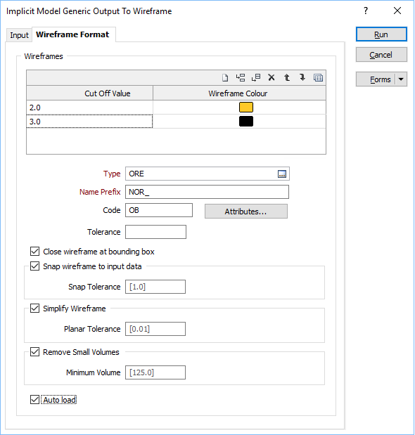
Use the Wireframe Format tab of the Generic Output form to generate wireframe output from an input implicit model file.
Wireframes
To generate wireframe output, select the Wireframes check box.
Cut Off Values and Colours
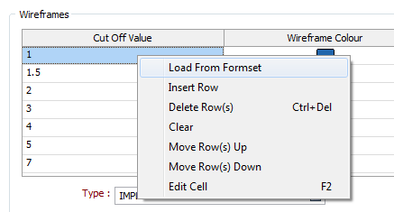
Use the grid to determine how many Result Wireframes will be output as a result of the process and the Colours to apply to each. You can populate the list by selecting a Numeric colour set from the right-click menu.
Each cut off value represents a lower cut-off. Given a value of 0.7, for example, the resultant wireframe will enclose values of 0.7 and higher.
Use the buttons on the grid list toolbar to Manage the rows in the list.
Type and Name Prefix
Double-click (F3) to select the Type of the output wireframe and specify a Name prefix.
Code
Optionally enter a Code attribute.
Tolerance
Specify a tolerance (in Grid units).
The surface extracted from the implicit model is done to the accuracy defined by the tolerance, such that the difference between the wireframe surface and the theoretically perfect mathematical model falls within the measured tolerance distance.
Quality
This setting provides a convenient way to control the quality and the speed of wireframe generation. There are five quality settings: Draft, Standard, High, Ultra and Custom.
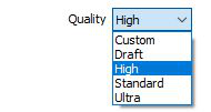
Setting the quality to Draft allows the general shape of the output wireframes to be generated quickly.
With the exception of Custom, each quality setting has a pre-set error tolerance value. The error tolerance for Draft is approximately twice that for Standard, which, in turn, is twice that for High, etc.
Setting the Quality to Custom allows a user-specified error tolerance. There is no limit to the user-specified error tolerance value (and hence the minimum mesh size), other than that imposed by available system memory.
Max triangle Size
To eliminate large meshes, specify a Maximum Triangle Size parameter in grid units.
By default, mesh size is controlled by the tolerance parameter, which specifies the maximum error between the rendered surface and the actual surface. Typically, larger meshes are used where the surface is relatively flat, and smaller meshes are used where the surface has high curvature.
If a Max Triangle Size is specified then all triangles will be that size, or smaller if they fail the tolerance test.
Attributes
Click the Attributes button to set attributes for the wireframe output.
If you want to map user-defined attributes against the fields in an Input file, use the form-based (Wireframe | Create from Strings | Centreline to Solid) function.
Close wireframe at bounding box
Select this option to limit the generated wireframe to the extents of the input data.
Snap wireframe to input data
The generated wireframes may be slightly offset from the points they were created from. Select this check box to snap the wireframes to the input data. Snapping will move the closest triangle to each snap point, if the distance between the two is less than the specified Snap tolerance.
If you do not enter a value, the default tolerance is 1 metre.
Simplify Wireframe
Select this option to reduce the number of vertices in the triangulation by eliminating those points that can be removed without causing the triangulation to move by more than the specified tolerance values:
- Planar Tolerance. This is the maximum amount that the triangulation is allowed to move in any direction after vertices are removed.
If no planar tolerance is specified, a default value of 0.01 will be applied automatically. Specifying a large planar tolerance will significantly alter the nature of the triangulation.
Remove small volumes
If this option is selected, all independent triangle shells with a volume less than the specified minimum volume will be removed.
Any value less than or equal to zero will disable volume removal.
Auto load
Select this option to load the generated output in Vizex. The default draw style for an auto-loaded wireframe is 3D Shaded.