Until you enter Edit Ring mode and select a ring, drillholes will not be displayed unless the "Always display drillholes" option is selected as part of your Drillhole Labels Display Options.
To create a drillhole fan:
- Click on the Edit Ring button to enter Edit Ring mode. If no ring is selected, the Selection Assistant will prompt you to select the ring you want to edit.

The orientation of the display will change so that it is orthogonal to the selected ring plane. If holes already exist on the current ring, they will be displayed.
-
Click on the Generate Drillhole Fan tool.

-
Digitise a pivot point. If you have setup a drill rig restriction, the pivot point will be an offset of the Boom Pivot Point, and must be located within the drive boundary.
For a drillhole fan, the pivot point for each hole remains constant, while the hole angle differs for each hole, based upon the specified angle range, toe spacing, and spacing algorithm.
The Status bar is displayed when a drillhole design tool is active and provides guidance when drillholes are being designed, for example, when the location of the drill rig is being defined:
Rig: Reports X and Y offsets from the ring centreline origin. These values can be utilized as a guide when defining the position of the rig within the drive boundary. Boom: Reports the rig’s boom X and Y offsets from the default location. These values can be used a guide when a user wants to displace the boom from the default position before drillholes are added. Pivot: Reports the final pivot point as an offset from the ring centreline origin. 
-
Once the pivot point has been digitised, move and then drag the mouse in an arc to define the angle range that the drillhole fan will cover.
- CTRL will move by increment / multiplier.
- SHIFT + LEFT/RIGHT ARROW keys will rotate by 5 degrees.
- SHIFT + UP/DOWN ARROW keys will straighten the rig (point the rig up/down).
- SHIFT + CTRL + LEFT/RIGHT ARROW keys will rotate by 1 degree.
When you have setup a Drill Rig Restriction in the Ring Design Options form:
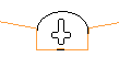
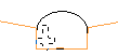
An outline of the rig shape is drawn around the cursor when new holes are designed. The rig outline is a solid line when the rig lies inside the drive (and is, therefore, in a valid position). If any part of the rig shape falls outside of the drive, a dashed line is shown.
You can use the keyboard to move or nudge the boom (the rotatable part of the rig) when designing new holes in Ring Design.
In Vizex, you can use the keyboard arrow keys to nudge selected strings or points in the plane of the screen, by a specified increment, or by a specified increment and multiplier.
The Up and Down arrows move the selected strings or points in a positive and negative Y direction. The Right and Left arrows move the selected strings or points in a positive and negative X direction.
The CTRL key can be used in combination with the arrow keys to modify the increment:
Nudge increment and multiplier values are defined as String Editing Options (Tools | Options | Vizex | String Editing). The nudge increment defaults to 1.0. The nudge increment multiplier defaults to 10.
For example, if the nudge increment is set to 1, and the nudge increment multiplier is set to 10, the arrow keys will move the rotatable part of the rig by 1, while CTRL + arrow keys will move it by 0.1.
The rig shape can also be rotated using the arrow keys:
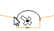
Once a valid rig position is selected and the mouse button is pressed, the rig shape will be anchored at that position. As the mouse is moved around, the boom of the rig shape rotates about the boom pivot point, again changing how the lines of the rig shape are drawn.
When the pivot point and the hole angles are edited, some basic checks are made against the rig shape to ensure that the rig position/boom rotation is valid.
For fans, the boom of the rig shape continues to rotate around the boom pivot point, again being drawn as a solid line when the end hole direction is valid for the rig shape.
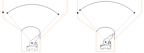
If you release the mouse button in an invalid rig position/boom rotation based on the hole direction, the tool will do nothing and you must select a valid direction and press the mouse button.
As you generate the drillhole fan you can also snap to an existing pivot point or hole. See: Snapping
-
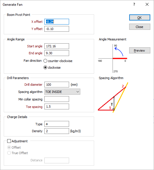
When you release the mouse button, the Generate Fan dialog is displayed:
-
The Start angle-End angle range and the direction of the fan you have defined interactively are displayed in the Angle Range group. Here you can adjust the Start and End angle values and, if necessary, change the (clockwise or counter-clockwise) fan direction.
Angles are measured within a 0° – 360° range (or within a -180° – 180° range if negative angles are included as part of your Drillhole Angle Options).
-
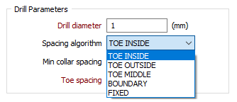
Enter the drill diameter, the toe spacing, and the spacing algorithm to be applied when generating the fan. The drill diameter is expressed in millimetres. The toe spacing is expressed in metres. See: Hole spacing algorithms
When non-parallel holes are generated, you can specify a minimum collar spacing which is the minimum distance between the holes along the DRIVE boundary. If the calculated distance is less than the minimum collar spacing, the minimum is applied instead.
-
If necessary, adjust the position of the pivot point. The displayed coordinates represent an offset from the drive string. The pivot point is measured from the intersection point of the drive string and the ring plane (the drive "centre line").
-
Enter the parameters that describe the type and density (in kg/cubic metres) of the explosives to be used for charging. Charge details can be included in a ring design report or plot.
-
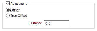
Use the Adjustment options to adjust the length of the drillholes and create stand-off between the toe of the holes and the excavation boundary.
Entering a positive value in the distance setting will result in over-drill whilst entering a negative value will result in an under-drill effect. The adjustment can be based on either a standard offset from the ring boundary or the true offset method.
-
Click the Preview button to see a preview of the holes that will be generated.
-
Finally, click the OK button to generate the drillhole fan.
You are not restricted to creating one drillhole fan. You can create multiple fans, and, where appropriate, combine them with parallel holes. To ease the process, you can snap to an existing pivot point or hole. See: Snapping
While you can use the mouse to move and rotate holes in the display, it is preferable to adjust the position and the angle of selected holes in the Properties window.
If you need to modify the position and angle of multiple holes, you can use the Adjust Multiple Drillholes tool on the Ring Design toolbar. Depending on the changes you want to make, it may be easier to delete those holes and recreate them using the Generate functions provided on the toolbar.