Semi Variogram Model Autofit
When you are ready to fit theoretical models to your experimental variograms, you will have a good understanding of your data, and the kind of model combination that will work best with your data.
To define this combination, the Semi Variogram Model Autofit dialog allows you to predefine the components of the model without having to fit them interactively using Chart Controls. This is critical for MIK modelling where tens, if not hundreds, of variograms will need to be modelled.
In order for the models to be properly fitted, the Use Variogram Control File check box option must be deselected on the Directional Semi Variograms form. If this option is selected, the parameters in the control file will override the autofit parameters you define here.
Click the Autofit Model button on the local toolbar, to automate the initial estimate of the nugget, ranges and partial sills.

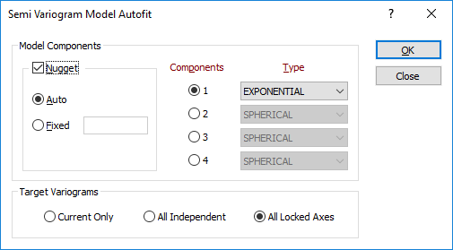
Model Components
Nugget
If you select auto and choose to calculate the nugget value automatically, the application will use the nugget of whichever 3D axis returns the smallest value. In practice, however, you will have estimated a more appropriate fixed nugget value from the downhole variogram.
Components
When you autofit a semi variogram model, associated range and partial sill values will be calculated automatically. Only the number of components, and the model type of each component, can be set (or updated).
Type
The type of model should have a general shape which resembles the experimental semi variogram. See: Types of semi variogram model
Target Variograms
Choose how the target variograms will be constructed:
| Current Only | Construct a model for the current variogram only. |
| All Independent | Construct independent models for all variograms. |
| All Locked Axes | Construct models for all variograms with Sill, Final Sill, Slope and Power parameters tied across all models. |