Profile Shape
Specify the following parameters on the Profile Shape tab of the Centreline to Solid form:

Choose the shape the extrusion will take. These shapes are self-explanatory (with the exception of the Trapezoids and the Three-centred Arch). The dimensions that you must enter in the adjacent prompts are displayed in the Preview window below the Shape list box.
Trapezoid 1 has its smaller dimension to the top of the display, which you enter in the Top(T) prompt. Trapezoid 2 has its smaller dimension to the bottom of the display, which you enter in the Bottom(B) prompt.
Top and Bottom Corner Radius
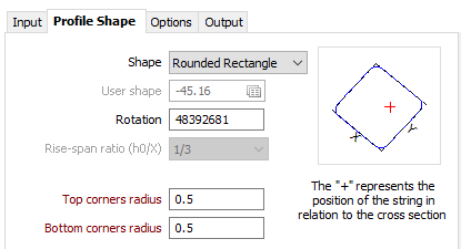
If you have chosen the Rounded Rectangle shape, you must specify the radius of the top and bottom corners.
User shape
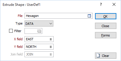
If you have selected User as the shape of the extrusion, double-click (or click on the Forms icon) to select the form set that contains the parameters of the user-defined shape. To create a form set, type a new set name, and then press F4 to create the form set. In the Extrude Shape form, specify the file and fields containing the X and Y coordinates that define the shape and optionally apply a filter to restrict the process to a subset of the records in the file.
If the current function supports the definition of multiple shapes, you can also specify a Join field.
The shape of the wireframe profile appears in the panel in the centre of the form and is altered when you enter or modify the dimensions. The position of the profile with respect to the string is also shown.
Rotation
Enter a value (0 to 360°) if you want to rotate the profile shape. Use positive or negative values to rotate in a clockwise or anti-clockwise direction.
Rise-span ratio
The Rise-span ratio options can be used to calculate the curve and the height of the arch when you select either Circular arch or Three-centred arch as the profile shape. You can also choose to explicitly define the arch height. The ratio is defined as:
h0 / x
where
h0 is the arch height
x is the width of the profile shape
Three commonly-used predefined ratios are available for selection.
If you choose to specify a Custom ratio, a Rise span ratio value can be specified under the Y Dimension group (see below).
X Dimension - Width
The X dimension of the extruded shape can be determined either by entering the width and a default X offset value, or by calculating the width as the sum of a Left Offset and a Right Offset (See: ‘X Dimension - Left + Right Offset’ below).
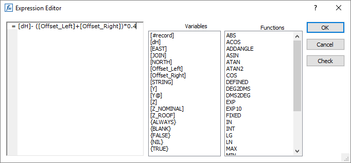
Dynamic field expressions are supported. See: Expression Editor
Width (X)
Enter the Width labelled as X in the panel showing the shape display. Optionally, double-click to select the name of a field containing Width values in the String file. The values in this field will be used to control the width of the extrusion.
X offset
Enter the distance the extrusion will be offset from the string in the X direction. Optionally, double-click to select the name of a field containing X Offset values in the String file.
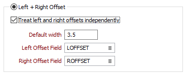
X Dimension - Left + Right Offset
When doing a pickup it is quite common to measure the Left and Right offsets from the centreline (at roughly regular intervals) to define the sidewall position.
Select this option to use Left and Right offset values (output from the Mining | Underground Design | Sidewall Centreline Offsets function) to set the X dimension of the profile shape.
Create asymmetric profile
The default action for an arched roof is to assume that the centre of the arch is midway between the sidewalls. However, sidewall variations can make this look “crinkly” and when there are cuddies (see the left-hand picture below) the result is unrealistic.
A better way to handle this is to calculate separate arches for the left and right hand sides of the profile. These meet at the position of the nominal centreline. So the “spine” tracks the actual centreline (see the right-hand picture below).
If the final result looks odd, you can adjust the centreline and offset values and re-run the process.
Default width
Enter a Default width. Where there is a missing Left or Right offset field value, the offset will be calculated as the default width - the known offset.
Left and Right Offset Fields
Double-click to select the name of the fields in the String file that contain Left and Right offset values.
Y Dimension
Height (Y)
Enter the Height labelled as Y in the panel showing the shape display. Optionally, double-click to select the name of a field containing Height values in the String file. The values in this field will be used to control the height of the extrusion.
Y offset
Enter the distance the extrusion will be offset from the string in the Y direction. Optionally, double-click to select the name of a field containing Y Offset values in the String file.
Arch height / Rise span ratio
These inputs apply to a circular arch, or a three-centered arch, created with a custom height/custom ratio.
- You can enter an Arch height value when the Custom Height option is selected in the Rise-span ration drop-down box (see above). If you select a predefined Rise-span ratio, the Arch height is calculated and displayed as a read-only field.
- You can enter a Rise span ratio value when the Rise span ratio option is selected in the Rise-span ration drop-down box.
You can obtain the Arch Height or Rise-span Ratio parameter from a field in the Input file. Where field values are blank, the value specified in the form is used instead.
If you are specifying a Custom ratio for the Circular arch, the value you specify must not be greater than 0.5.
Top (T)/Bottom (B)
If you have chosen one of the trapezoid shapes, enter a value for the narrower dimension in the Top or Bottom prompt (the prompt changes according to which of the trapezoid shapes you have chosen).
The shape and dimensions of the wireframe profile appear in the panel in the centre of the form. The position of the profile with respect to the string is also shown.
The Width and Height fields are optional if a User shape is selected and you are using width to determine the X dimension. If they are blank, the width and/or the height will be taken from the string used to represent the shape.
For a non-user shape, a Width/Height value is still required even if you have specified a Width/Height field. This will be used as the default when a value in the Width/Height field is blank.