Underground Mine & Ring Design
Generate Ring Boundary
This new tool eliminates the need to manually design boundaries for ring blasts.

|
When you click the Use wireframe to auto-generate boundaries tool, a 2D slice of the stope wireframe, at the position of each ring along the drive, is used to generate a ring boundary. The tool is applied to selected rings along the drive, or if you have selected a drive string, all rings along the drive. |
For more information, see: Auto generate boundaries from wireframe
Charge Energy Distribution
A new function allows you to calculate a Charge Energy Distribution grid that can be used to validate ring patterns and their explosive charging.
For more information, see: Charge Energy Distribution
Charging Method
The drillholes of a ring can now be automatically charged using one of two methods:
- AEL approach
- Influence Radius
For more information, see: Charging Method
IREDES Import and Export
You can now import a Ring Design in IREDES file format.
International Rock Excavation Data Exchange Standard (IREDES) is an industry standard to unify routines for the data exchange between mining equipment and office computer systems. The input/output file type is XML.
The Import function complements an IREDES export function on the same menu. There are now two export format options:
| Sandvik | The Lowest Pivot Point is used as the origin to transform the design coordinates to rig drill plan coordinates. This point then becomes point 0,0,0 on the rig. Holes are exported in transformed coordinates such that the Pivot point for the hole is the start of the hole and the Toe point is the end of the hole. |
| Atlas Copco | The Reference Point is used as the origin to transform the design coordinates to rig drill plan coordinates. This point then becomes point 0,0,0 on the rig. Holes are exported in transformed coordinates such that the Collar point is the start of the hole and the Toe point is the end of the hole. |
Replicate Ring
A new "Spacing measured..." option allows a ring to be replicated by a specified real distance measured from the previous ring, or by a specified distance measured along the drive string.
Note: It is important to note the difference that the "Use ring azimuth" option makes to the Spacing measured by real distance option. When the Use ring azimuth option is selected, all rings are replicated with the same azimuth, parallel to one another, and the spacing is the direct distance between them.
When the Use ring azimuth option is not selected, rings are replicated perpendicular to the drive. In this case the spacing represents the distance between the previous ring and the next parallel projection of a ring.
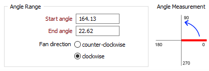
Drillhole Fan - Angle Measurements
Angles that are defined interactively are now set within a 0° – 360° range (or a -180° – 180° range if negative angles are included as part of your Drillhole Angle Options) and in a direction now indicated by Fan Direction radio buttons on the Generate Fan form. This removes the ambiguity as to which portion of the circle is represented by the specified Start and End angles.
Angle values outside of a 0° – 360° (or -180°180°) range are not allowed when generating a fan, parallel drillholes, or a single drillhole.
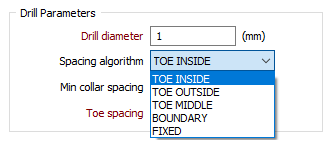
Toe Spacing
The TOE spacing algorithm, used when you generate a drillhole fan or a single relative drillhole, is now separated into TOE INSIDE and TOE OUTSIDE options. The distance is always perpendicular to the current drillhole and is taken from either the end of hole or (if not applicable) from the end of next hole.
For more information, see: Hole spacing algorithms
Underground Tools
The following underground tools have been enhanced in this release:
- Sidewall to Solid: You can now set the shape of the extruded solid using the Profile Shape tab of the form. You can also run an (Interactive) function and select the sidewall strings (and optional roof and floor restriction points) in Vizex.
- Sidewall to Centreline: You can now select a Straighten (remove points) option to straighten the centreline by removing intermediate points.on segments.
- Sidewall Centreline Offsets: A Height Calculation by roof points option has been added to the form.
No straightening will occur when the slider is set to None. The more points you choose to remove (by moving the slider towards Many) the straighter the result will be.
Block Model Tools
The block modelling tools that mining engineers typically need to create, restrict, assign, sub-block, and interpolate blocks, etc, are now provided as part of the Mining module:
- Modelling | Block Model Tools | Create Blank
- Modelling | Block Model Tools | Setup
- Modelling | Block Model Tools | Validate
- Modelling | Block Model Tools | Reblock
- Modelling | Block Model Tools | Reblock with Rotation
- Modelling | Block Model Tools | Combine
- Modelling | Block Model Tools | Optimise
- Modelling | Block Model Tools | Regularise
- Modelling | Block Model Tools | Convert Imported Data to Block Model
- Modelling | 3D Block Estimate | Inverse Distance Weighting
- Modelling | Reporting | Block Model