Pit Design
Before you begin the pit design process, load any display objects that define the area of interest, for example, an ore body block model and an optimal pit wireframe that can be used as a guide during design.
Select Mining | Pit Design | Open (or Display | Pit Design) to open the Pit Design form.
Input Data
On the Input Data tab of the Pit Design form, define the default settings to be applied when you use the string editing tools to generate the slopes, batters and berms for sectors at various levels within the pit outline.
File
Double-click (F3) to select and load an existing Pit Design file. A *.PIT file is a string file which has an additional ROAD field. To create a new pit design file, right-click in the file input box and select New from the right-click menu.

When creating a new layer in Vizex, a template which defines the structure of a Pit file is applied automatically.
Parameters
There is a direct trigonometric relationship between the Interramp (Slope) angle, the Batter height, the Batter slope, and the Berm width.
The Calculate button allows you to calculate any one of the following 4 values by leaving one value blank and varying the other 3. The Interramp angle, for example, can be calculated from the Batter height, the Batter slope, and the Berm width. Alternatively, enter a Batter height, a Batter slope, and a required Interramp angle, then click Calculate to calculate an appropriate Berm width.
If all 4 values are specified, clicking the Calculate button will recalculate the Interramp angle. If less than 3 values are specified, you will be prompted to specify at least 3 values.
If a Constraints model is used, then the Batter Slope and the Berm Width values specified in that file will be used instead of the default values.

Design mode
Select a Pit or Dump design mode which will determine how the walls of the pit or waste dump will be projected (Out or In, respectively) using the Project String, Project To Berm and Expand String tools on the Pit Design Toolbar.
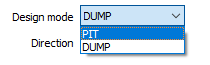
Direction
Select an expansion direction. Typically, you will select PIT as the design mode and choose an UP direction to generate a pit up and out from a digitised base string. Note that you can also set the direction from the Pit Design toolbar.
When designing up and out, points are automatically inserted. When designing down and in, this automatic point insertion is disabled, since in most cases you will want to “simplify” rather than add points to each new crest string.
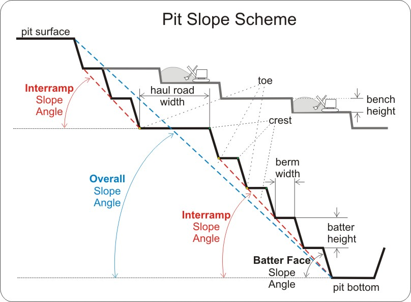
Interramp angle
The Interramp angle is the slope angle produced by a number of benches. (It is assumed that the Batter Slope, Batter Height and Berm Width are constant).
The overall slope angle, on the other hand, is the angle of a line from the toe at the bottom of the pit, to the crest of the pit surface. Since this slope takes into account the haul roads and all working levels, it will not be constant at all parts of the pit.
It therefore follows that the Interramp angle will be steeper than the overall slope angle, and this must be taken into consideration during the pit design.
Batter height
The Batter is the sloping face of a pit wall between two consecutive berms. The Batter height is the vertical distance between each consecutive toe and crest. It is the Batters that form the final pit limits.
A "bench', on the other hand, is an operational open-pit concept. A bench can be defined as a ledge in an open-pit mine from which excavation takes place at a constant level. When benches achieve the final pit limit they form a pit 'batter'.
Batter slope
The Batter slope is the default angle, measured from the horizontal, between successive toe and crest strings. The angle is measured in degrees to 2 decimal places and the angle value should be greater than 0 and less than 90.
Berm width
The Berm width is the horizontal distance between a toe and a corresponding crest at the same level.
Contour interval
A Contour interval value is used to generate additional contour strings between successive toes and crests, for example, to denote benches. You can use the Contour interval to design sub-benches with a different road width. The Batter height must be a multiple of the Contour interval value.
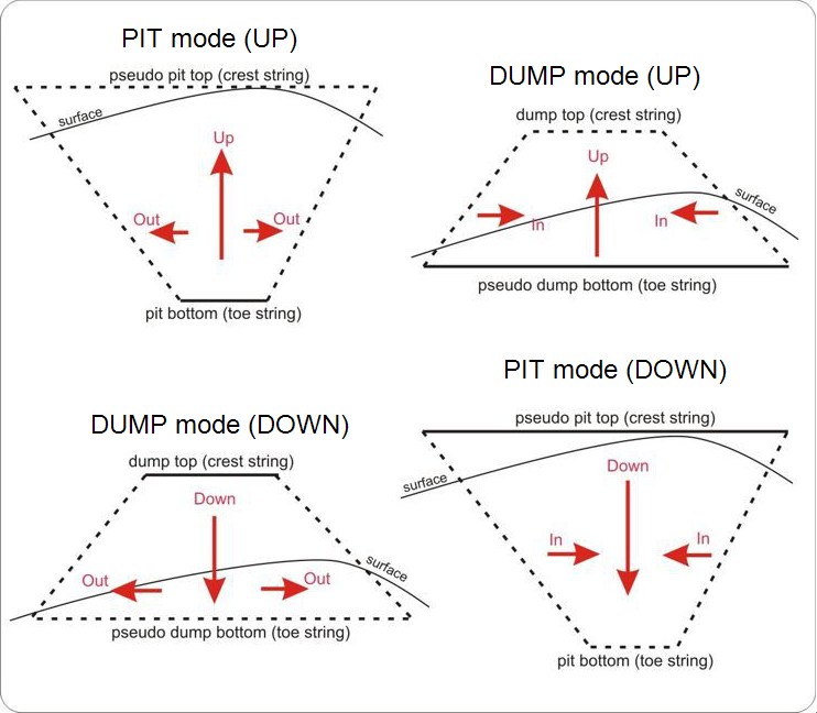
Berm Inclination
Sometimes a slope may need to be designed into the berms in order to collect water or stone fragments against the pit wall. If this is the case, select the Berm Inclination option and enter a Gradient value. The value you enter should fall between 0 and 10 (typically 5 or 10) %.
When a Berm gradient value is specified, an additional contour string is shown in the design, alongside the crest, toe, and road strings. This contour string represents a "pseudo" toe, in other words, it denotes where the toe would be without the berm gradient. ![]() Show me...
Show me...
When a Pit Design layer is the active layer, Batter height, Batter slope and Berm width design parameters are shown on the Pit Design Toolbar, where they can be easily edited.
Road and Berm Default Parameters
By default, full-width berm access is allowed at both the CREST and the TOE when you add a road to the pit. However, you may choose to change the default behaviour:
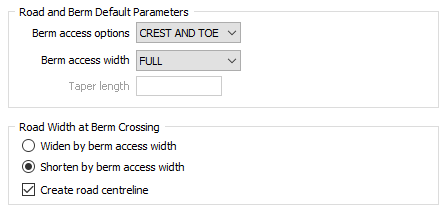
Berm access options
Specify how the berms will be accessed from the roads. In situations where you do not need to access every berm, you can choose to restrict access to the CREST or the TOE, or select the NONE option to disable berm access completely.
Berm access width
Where a berm is accessed by a road you can choose to make the access width the FULL width of the berm, or HALF the width of the berm. You may want to restrict berm access to people, rather than vehicles, for example.
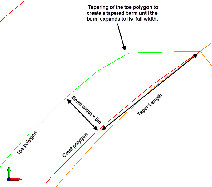
Taper length
This input is enabled when NONE is selected as the Berm access option. An algorithm is applied to automatically calculate the length of the taper. However, if you want the berms to be tapered at a specific length, enter a value. The length of taper is the distance from the road crossing to the place where the taper starts.
You will receive a warning if the specified taper distance is not appropriate for the pre-defined design parameters. Specifying an inappropriate taper distance may lead to incorrect ramp projections.
Road width at Berm Crossing
If Berm access is enabled, choose to use the specified Berm access width to Widen or Shorten the width of the road at the berm crossing.
Create road centre-line
Select this option to display a road centre-line.
In order to end up with an accessible road, when you set the Road width, you may need to take into account the Berm width (if Berm access is enabled as part of your design parameters).
Enable automatic cross over repair
When you use the Project String, Expand String, and Project To Berm tools to generate design strings, the strings may occasionally be crossed over, due to defects or kinks in the string which cannot immediately be detected and resolved.
Select this option to automatically fix any cross-over strings that occur as the walls of the pit are generated.
Auto fillet
The Auto fillet option applies whatever fillet radius is needed to determine the arc of curve. Acute angles are automatically smoothed, so in some cases you may prefer to turn this option off.

Forms
Click the Forms button to select and open a saved form set, or if a form set has been loaded, save the current form set.
By design the Forms button is not available for loaded Vizex layers (i.e. when opening the form set properties of a layer in the Display Pane). In Vizex, the Forms button is only available for new forms opened via the Display | Vizex menu (or by double-clicking on a form type node in the Vizex Forms Pane).
Save and Save As
Click the Save button to save the changes you have made to the form set. Click Save As to save your changes as a new form set. Save As will default to the first available form set number.
Reset
Click Clear to clear the form of all values and reset the form to its default state. In the case of tabbed forms, set the first tab as the active tab.
Undo and Redo
Click Undo (CTRL + Z) to undo recent changes in the form. After an Undo, click Redo (CTRL + Y) to restore the last change that was undone.
Collapse
Collapse (roll-up) the form to preview a chart, or preview the results of an operation in Vizex, or obtain input values from Vizex, the Property Window, the File Editor, or the Plot Editor.