Setup
When you use the Survey | Convert Coordinates Between | Setup form to define a new coordinate conversion, there are three ways to choose the From and To coordinate systems, which you can mix and match as required:
- EPSG: Search for each coordinate system by name, or enter the EPSG (European Petroleum Survey Group) code if you already know it. For example, the geographic WGS84 coordinate system has the EPSG code 4326. This method is ideal for converting between recognised coordinate systems.
- Local: Create a form set that defines a local (plane grid) coordinate conversion. This method is best when you need to convert between a local mining coordinate system and any other recognised coordinate system.
- Advanced: Define your own coordinate system by writing a sequence of parameter names and their values.
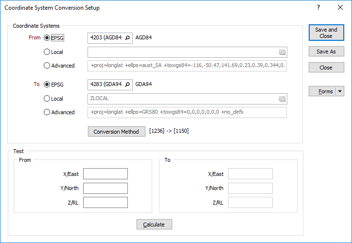
EPSG
To search for an EPSG coordinate system:
- Click the Search button at right of the EPSG response and start typing any part of the coordinate system name.
- When you stop, Micromine will display the names that match your text.
- Once selected, Micromine displays the EPSG code and matching coordinate system name in the Setup form; choose the relevant name.
- OR, if you already know the EPSG code, simply enter it directly into the EPSG response on the form.
Grid shift file
Micromine will notify you if a conversion has an available grid shift file, which usually applies to conversions between modern and historic coordinate systems. To use a shift grid file:
-
Click the Conversion Method button to display the Conversion Method dialog.
- Click the Browse button at right of the Grid shift file response and choose the file.
- Be sure to use the file appropriate for your conversion.
This option is only enabled for specific conversions. For information on obtaining a grid shift file, visit the Coordinate System Resources page.
Background: Some conversions between historic and modern coordinate systems can’t be accurately described using a handful of parameters. This happens when historic coordinate systems contain local errors and irregularities that make them inaccurate by today’s standards. To overcome this limitation, modern conversions rely on shift grids (also known as transformation, distortion, or difference grids) to produce the most accurate result. A shift grid is simply a 2D mesh that covers the region of interest (typically a province or country), where each node in the mesh accurately defines the X and Y positional errors at that location. Applying the conversion is a case of interpolating the node values surrounding the location under investigation and using them to adjust the coordinate values.
Local
A local coordinate system requires a widely-spaced pair of tie points whose coordinates you also know in a recognised projected coordinate system. Spacing the tie points as far apart as possible will improve the accuracy of the resulting conversion.
To create a local coordinate system:
- Right-click the Local response and create a new form set.
- Enter the X and Y coordinates of two points in the local coordinate system.
- Supply the EPSG code of the tie point coordinate system, which must be a projected coordinate system like Universal Transverse Mercator.
- Enter the tie X and Y coordinates of the tie points in the tie point coordinate system.
- Use the Validation results to ensure that the conversion is correct. (A scale value a long way from 1, or an unexpected rotation, are obvious signs of an error.)
Background:
A local coordinate system is one where the earth is assumed to be flat, with rectangular X, Y, and optionally Z, coordinates. This assumption is suitable for project areas a few tens of kilometres in size and is common for mining projects.
Your surveying department would generally supply the local coordinate system information, and may also provide you with rigorous conversion parameters relative to the tie point system.
Once a local coordinate system has been defined it can be used to convert to or from any other coordinate system. This makes it possible, for example, to:
- Convert directly from WGS 84 geographic coordinates captured by your GPS into your local coordinate system, to simplify survey pickups and field mapping;
- Convert directly from your local coordinate system to WGS 84 geographic for uploading to a GPS, to simplify drillhole pegging and other setting out activities.
Advanced
The Advanced option provides a way to construct a coordinate system by specifying individual parameters and their values. It is best suited to creating a custom coordinate system or reconstructing a historic coordinate system.
Defining an advanced coordinate system requires knowledge of PROJ string syntax. To learn more about creating an advanced coordinate system, visit the Coordinate System Resources page.
Test
Use the test area to check your conversion parameters against official reference data. To do so:
- Enter the X, Y, and optionally Z, coordinate values.
- If the conversion includes latitude/longitude values, choose the required Geographic coordinate units.
- Click the Calculate button and inspect the results.
Forms
Click the Forms button to select and open a saved form set, or if a form set has been loaded, save the current form set.
By design the Forms button is not available for loaded Vizex layers (i.e. when opening the form set properties of a layer in the Display Pane). In Vizex, the Forms button is only available for new forms opened via the Display | Vizex menu (or by double-clicking on a form type node in the Vizex Forms Pane).
Save and Save As
Click the Save button to save the changes you have made to the form set. Click Save As to save your changes as a new form set. Save As will default to the first available form set number.
Reset
Click Clear to clear the form of all values and reset the form to its default state. In the case of tabbed forms, set the first tab as the active tab.
Undo and Redo
Click Undo (CTRL + Z) to undo recent changes in the form. After an Undo, click Redo (CTRL + Y) to restore the last change that was undone.
Collapse
Collapse (roll-up) the form to preview the results of an operation in Vizex, or obtain input values from Vizex, the Property Window, the File Editor, or the Plot Editor.