Wireframe Tools
Wireframing tools are provided on the Wireframe Editing Toolbar and Wireframe Tools toolbars. If a layer is not already active, you will be prompted to select a triangulation layer or a tie lines (strings) layer as the Active Layer.
To quickly open or close a toolbar, right-click in an empty space below the menu bar, then select a toolbar from the right-click menu. A check box is shown alongside those toolbars that are currently open.
The width of the application window, and the selections you make when customising the toolbar, will determine which tools are visible.
|
|
Click the Manage Attributes tool to display and edit the attributes of the wireframes you have selected interactively. See: M |
|
|
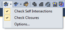
Select an option from the Validate Wireframe tool menu to validate a wireframe and check for self-intersection, closure, and invalid topology. You can also set (Tools | Options | Vizex) Wireframing. |
|
|
|
|
|
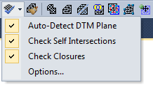
Select an option from the Validate DTM tool menu to perform Wireframe Validation and check that a wireframe is a Validate DTM. You can also set (Tools | Options | Vizex) Wireframing. |
|
|
|
|
|
Click the Clean Wireframe button to perform a Wireframe Clean on a selected wireframe. The Clean operation will clean and repair the wireframe by removing unnecessary points and triangles. Point snapping is performed automatically as part of the operation. |

|
Click the Save As Single Wireframe button (also available via the the right-click Selection menu) to save the wireframes selected in Vizex as a single wireframe. |
|
|
For more information, refer to the Save as single wireframe topic. |

|
Click the Save As Wireframe Set button (also available via the the right-click Selection menu) to save the wireframes selected in Vizex as a wireframe set. |
|
|
For more information, refer to the Save As Wireframe Set topic. |
|
|
Select Create DTM from the tool menu to generate a DTM from the strings and points selected in the display. See: Generate a DTM |
|
|
Select Create Floor Wireframe from the tool menu to generate a declined or multi-level surface wireframe from the strings and points selected in the display. See: Create Floor Wireframe |
|
|
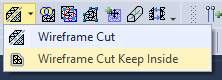
To cut a wireframe by extruding a polyline, select an option from the Wireframe Cut tool menu. See: Cut and Cut Keep Inside. |
|
|
|
|
|
Click the Boolean Commands tool to perform an Boolean Commands operation on two or more intersecting wireframes. |
|
|
Click the Boolean Intersection Strings tool to perform a Boolean Commands operation on two or more intersecting wireframes and generate the intersection strings. |

|
Click the Silhouette tool to create a Silhouette edge polygon for one or more wireframes selected in the display. The generated strings or outlines are flattened to the current projection plane. You can also create wireframe silhouettes and write them to an output file via the Wireframe | Silhouette menu option. |

|
To copy, move, or replicate a wireframe by a specified amount, click theCopy/Move button. |
|
Click the Copy Selected Wireframes button (or select the Copy Selected Wireframes option from the right-click menu) to copy the wireframes or the CAD wireframes currently selected in the display to the active layer. If the active layer is not a Wireframe layer, you will be prompted to select a Wireframe layer as the active layer. If the wireframes you have selected are already in the active layer, they will still be copied. If you use the mouse to move the copied wireframes, the original wireframes will be visible underneath. |
|
|
|
Click the Centreline String to Solid button to convert one or more strings into a wireframe. You can use it, for example, to generate a wireframe from a series of strings that define underground features such as drives. See: Centreline to Solid |
|
|
Click the Snap tool to perform a Snap operation on one or more selected wireframes. Using a specified Snap tolerance, the process will remove any discrepancies that result from numerical precision problems on shared triangles. See: Snap |